A Decade of Discovery in Rotorcraft Simulation with NASA Supercomputing
Overview
Rotorcraft vehicles rely on spinning rotor blades to provide the thrust needed for vertical takeoff and landing, and the propulsive force required for forward flight. Examples include the UH60 Blackhawk helicopter, V22 Osprey tiltrotor, and a new class of green aircraft known as Urban Air Mobility (UAM) vehicles. Computational fluid dynamics (CFD) is a powerful tool that, when coupled with supercomputers, can numerically simulate the complex and time-varying flows produced by rotating blades with unrivalled detail.
However, in 2009, the average CFD prediction accuracy for rotorcraft hover performance differed from experiment by 2.4%. The importance of this seemingly small discrepancy can be appreciated knowing that an error of about 0.5% is equivalent to the weight of one passenger! The big question at the time was, why is CFD performing so poorly?
Project Details
NASA’s Revolutionary Vertical Lift Technology (RVLT) Project invested significant resources over the last decade to understand these shortcomings and improve the prediction accuracy of CFD methods. High-fidelity CFD simulations use numerical algorithms to solve time-dependent Reynolds-averaged Navier-Stokes (RANS) equations, which, along with a turbulence model, contain all the relevant physics needed to model rotorcraft flows. A careful study was undertaken to improve simulation accuracy and better understand how numerical choices affect the physics of hover and forward flight.
Results and Impact
Over the past decade, CFD researchers at the NASA Advanced Supercomputing (NAS) facility at Ames Research Center have achieved tremendous improvement in prediction accuracy, including the discovery of previously unknown flow phenomenon in the rotor wake. Research was first directed toward the V22 Osprey rotor in hover, and four key issues were identified and addressed in the CFD solution process: 1) improved the spatial accuracy of the numerical algorithm; 2) improved the standard turbulence model to a hybrid RANS/Large Eddy Simulation (LES) model, known as Detached Eddy Simulation (DES); 3) refined the rotor wake grid resolution; and 4) developed a quick-start procedure to reduce the computer simulation time by fourfold. These advances reduced the CFD error for rotorcraft from 2.4% to 0.2%—an order-of-magnitude improvement at a quarter of the computational cost.

Moreover, researchers efficiently refined the rotor wake below the blades using automated adaptive mesh refinement (AMR), where refined Cartesian meshes were dynamically applied to accurately capture the details of a constantly changing turbulent flow. This resulted in an unexpected discovery: the rotor wake was much more complex than previously thought, as worm-like turbulent structures (see image at right) appeared with grid refinement. The physical process for the formation of these turbulent “worms” was revealed by studying time-dependent flow visualization. Vorticity, a fundamental flow quantity that represents the spinning nature of the flow, is first formed along the rotor blades due to friction (viscosity) and descends downward as a helical sheet. When these sheets pass by a tip vortex, they are pulled into the vortex, much like a tornado pulls in objects along its path. This results in higher vorticity through a process known as vortex stretching, similar to how ice skaters pull in their arms to spin faster. The process that produces the worms stunned the rotorcraft community and resulted in several hover workshops to examine this phenomenon. Was it real or a numerical artifact? Finally, eight years later, an experimental technique known as tomographic particle image velocimetry successfully proved the turbulent worms are in fact real and physical. This demonstrates the power of discovery made through supercomputing.
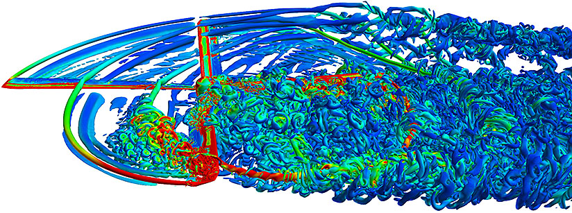
The dynamic AMR process was also applied to a UH60 Blackhawk helicopter while experiencing dynamic stall in forward flight. It was previously thought that dynamic stall was solely due to a rotor blade pitching up to a high angle of attack, causing a sudden loss of lift and increased blade vibration. However, simulations showed, for the first time, that blade-vortex interaction (BVI) can also cause dynamic stall, as shown in the image at left. As the tip vortex from another blade passed over the blade in the figure, the direction of spin of the vortex caused the outboard angle-of-attack to increase too much, triggering flow separation and stall. On the other hand, the inboard angle-of-attack was decreased, keeping the flow attached, and continued to provide lift.
Why HPC Matters
None of this rotorcraft CFD progress would have happened without access to NASA supercomputing resources and advanced time-dependent flow visualization. Rotorcraft flows often require from several hundred million to a few billion grid points to resolve flow details. Typical CFD simulations can take 1,000 – 6,000 processor cores running 24/7 for several days to a couple of weeks on the agency’s Pleiades and Aitken supercomputers. Data written out to disk can easily exceed 100 terabytes to generate each animation. This data output provides the most convenient way to explore unknown features in a flow field.
What's Next
One remaining mystery is the premature vortex breakdown of tip vortices in the AMR simulations of the V22 Osprey rotor in hover. This seems to be triggered by vortex pairing, where two separate vortices from different blades wrap around each other like a pretzel. Further research is needed to understand the numerical cause of early vortex breakdown and its remedy.
More Information
- Hammering Away at the Dynamic Stall Problem to Build Better Rotorcraft
- Quantitative Approach for the Accurate CFD Simulation of Hover in Turbulent Flow (PDF)
- Numerical Simulation of Dynamic Stall Using Near-Body Adaptive Mesh Refinement (PDF)
Researcher
- Neal M. Chaderjian, NASA Ames Research Center Please enable Javascript to see email address.