Simulating Moving Valves for Space Launch System Liquid Engines
Overview
Three-dimensional, time-accurate computational fluid dynamics (CFD) analysis of moving valves offers tremendous insight for valve design and operation. However, due to a lack of computational resources, CFD analysis of transient valve motion has rarely been performed as part of a valve design process.
In some valve applications, such as the Space Shuttle Orbiter Flow Control Valve (FCV), the first sign of significant fluid dynamics caused by valve actuation was the fluid-induced, high-cycle fatigue failure of the valve poppet. CFD analysis performed at NASA Marshall Space Flight Center identified fluid mode shapes and amplitudes that could have caused the FCV to fail, and showed that the conditions leading to the failure occurred at some point during valve actuation. However, due to limitations of the CFD tools and processing power available in 2009, all analyses were performed with the valve in a fixed, static position. The inconclusive results of the static position analysis and the associated delays in the shuttle flight schedule caused by the valve failure emphasized the need to develop the capability to perform time-accurate CFD analysis of moving valves.
Project Details
Researchers at Marshall Space Flight Center have since developed this capability using the density-based fluid analysis program Loci\CHEM. Due to the code's efficient parallelization and the increased supercomputing resources available at NASA Ames Research Center, these simulations can now be completed quickly enough to support valve design cycles.
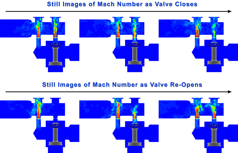
For this project, researchers modeled the opening and closing cycle of a candidate Space Launch System FCV to evaluate potentially damaging unsteady fluid environments in the valve poppet, and other critical performance metrics. Simulations were conducted using Loci\CHEM with an overset mesh method to simulate the moving valve components. A hybrid unstructured mesh with about 55 million cells was required to resolve the fluid dynamics of interest. A hybrid Reynolds-averaged Navier-Stokes/large eddy simulation (RANS-LES) turbulence model was used to accurately capture time-accurate pressure oscillations in the flow.
Results and Impact
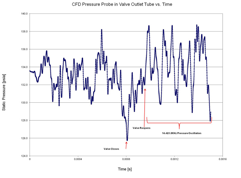
CFD analysis of the moving valve quantified the unsteady forces on the poppet head due to pressure changes during actuation, identified the onset of a periodic pressure response in the flow that occurs only after the valve re-opens, and showed that the tool access ports downstream of the flow orifices contributed to a 14-kHz pressure oscillation in the flow. A recommendation to fill the holes with inserts was given to the valve vendor, who recognized the benefit of eliminating this source of unsteady fluid environment and incorporated the recommendation into the design.
Role of High-End Computing Resources
In order for the CFD analysis to provide input for the valve design cycle, simulations were massively parallelized on NASA's Pleiades supercomputer. Simulations were performed using approximately 600 processors in order to complete one closing and re-opening cycle in a working week.
Brian R. Richardson, NASA Marshall Space Flight Centerbrian.r.richardson@nasa.gov