
Assessing Liquid Rocket Engine Feed Line Flow for the Space Launch System
Overview
The liquid propulsion system of NASA's Space Launch System (SLS) consists of fuel tanks, valves, propellant ducts, and liquid rocket engines. From a structural perspective, there are many differences between these elements, but from the perspective of the propellant, there is no distinct boundary between them. Engine and duct components must be designed to withstand flow environments generated by this integrated fluid system. Our work assesses the flow environment in the SLS liquid hydrogen (LH) feed line, upstream of the RS-25 engine's low pressure fuel pump (LPFP) for nominal RS-25 operation during the ascent phase of the SLS.
Project Details
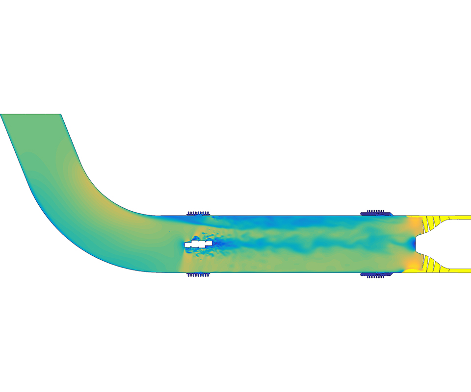
To simulate these elements of the SLS, we used the Loci/CHEM software, a C++ library and declarative programming framework being utilized at NASA's Marshall Space Flight Center. Simulation cases were run with full-scale geometry and liquid hydrogen as the fluid. Three distinct cases were modeled: the SLS LH feed line with no angulation and no inducer; the SLS LH feed line with no angulation, coupled to RS-25 LPFP; and the SLS LH feed line with 4.5 degrees gimbal angle, coupled to RS-25 LPFP.
The section of the SLS propulsion system modeled in this work includes an LH duct bend, a ball-strut tie rod joint, a gimbal joint, and the RS-25 LPFP. The simulations utilize operating conditions (for example, LH temperature, pressure, flow rate, and pump speed) from nominal operation of the RS-25 (109% rated power level). Simulations were run with single-phase calculations—that is, with no vapor formation.
If the flow to the pump is not suitably uniform, the pump performance and operating margins could be degraded. A non-uniform flow environment could also create radial loads on the pump bearings, which could cause excessive bearing wear. Therefore, flow uniformity was calculated for the three cases and compared. The various sources of flow variation were identified and their relative contribution to the flow field was determined.
Results and Impact
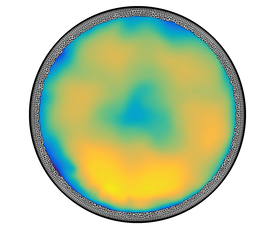
The LH duct geometry and components do generate a strictly non-uniform flow field, but the LPFP is the largest contributor to flow non-uniformity near the feed line/engine interface. This is due to the proximity of the LPFP to the interface location and the swirling backflow through the blade tip gaps near the duct walls. Duct angulation at the gimbal joint may also have a small effect on the pump backflow environment. The evaluation of the simulation data is ongoing, but the current configuration appears to have an acceptable flow environment.
Future work will entail an examination of forces and moments on LPFP blades as well as assessment of any changes in pump steady performance due to duct angulation.
Why HPC Matters
Modeling the full-scale geometry with fine details (such as, realistic LPFP tip clearances) requires more than 450 million volume mesh elements, which is only feasible to run with a computing resource like the Pleiades cluster at the NASA Advanced Supercomputing (NAS) facility at NASA's Ames Research Center.
Andrew Mulder, NASA Marshall Space Flight Centerandrew.d.mulder@nasa.gov