Modeling Self-Excited Combustion Instabilities
Overview
Self-excited combustion instabilities result from a combination of the acoustic pressure fluctuations and heat input from combustion. Because rocket combustion is so complex, these instabilities have plagued designers since the 1940s. Advances in computational capabilities, coupled with companion experiments, are now providing insights into the underlying multi-phase, multi-scale physical processes that can lead to engineering solutions.
Project Details
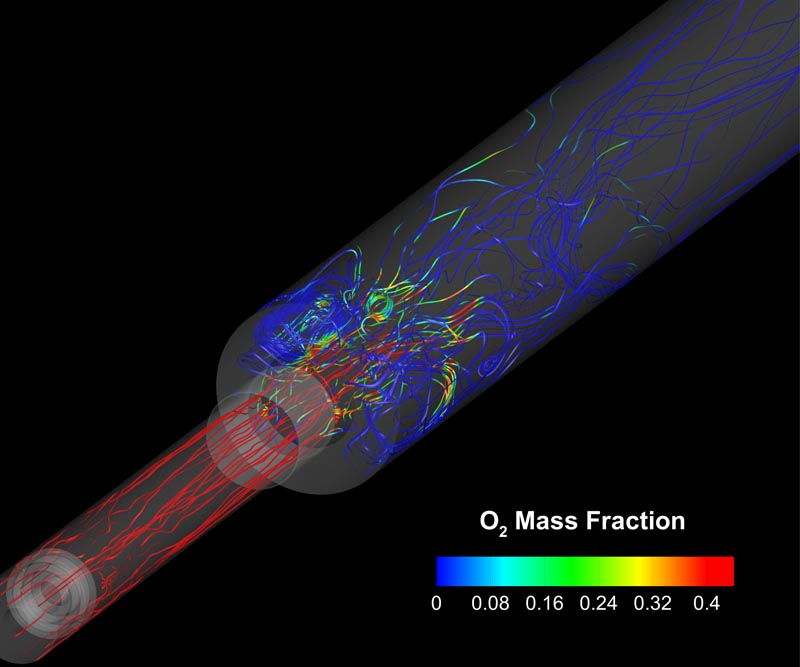
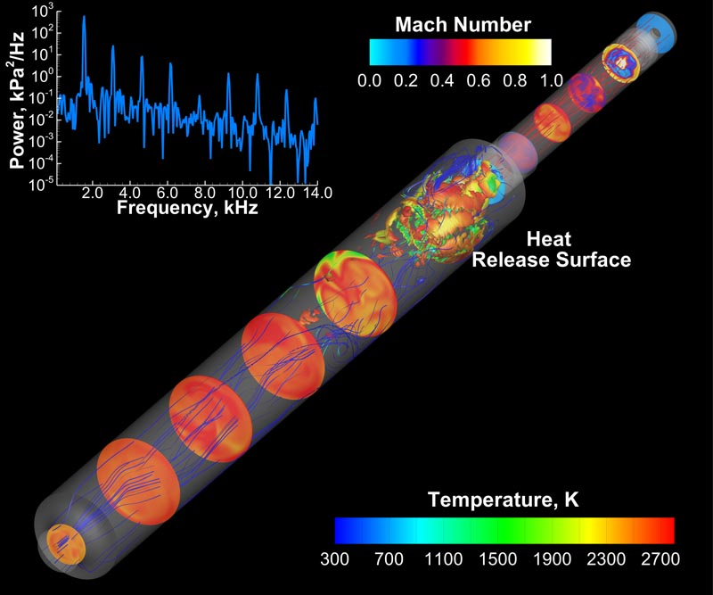
Computational fluid dynamics (CFD) simulations of an unstable, model combustor have been performed to gain a better understanding of the basic physics of combustion instabilities, and to verify the model. To capture the physics accurately, the unsteady flowfield and heat released due to combustion must be calculated simultaneously.
By conducting these simulations in parallel with experiments, we are able to both validate computational models and improve experiments in tandem. Once validated, the CFD simulations provide a wealth of detailed data that are not available from the experimental measurements alone.
Results and Impact
Use of a validated model during the combustor design phase serves to identify and mitigate potential sources of instabilities. The locations of substantial driving and damping regions are of particular interest. These regions can be identified by examining the correlations between pressure and heat release.
Our results have shown that most of the damping and driving mechanism are localized in the shear layer between the bulk axial flow and the recirculation region of the combustor.
Role of High-End Computing Resources
NASA supercomputing resources enable detailed, three-dimensional simulations to be run for extended durations that would otherwise be unattainable. Long simulation times are required in order to resolve the limit cycles of the instability. The Pleiades supercomputer allows for significantly faster runtimes than previous computers used for these simulations.
Matthew Harvazinski, Purdue Universitymharvazi@purdue.edu William Anderson, Purdue University
wanderso@purdue.edu